NOTICE: This software (or technical data) was produced for the U.S. Government under contract, and is subject to the Rights in Data-General Clause 52.227-14, Alt. IV (DEC 2007). Copyright 2024 The MITRE Corporation. All Rights Reserved.
Detection Chaining
The OpenMPF has the ability to chain detection tasks together in a detection pipeline. As each detection stage in the pipeline completes, the volume of data to be processed in the next stage may be reduced. Generally, any detection tasks executed prior to the final detection task in the pipeline are referred to as preprocessors or filters. For example, consider the following pipeline which demonstrates the use of a motion preprocessor:

In the pipeline above, the motion preprocessor reduces the volume of data which is passed to the face detector. This is particularly useful when the input media collection contains videos captured by a fixed-location camera. For example, a camera targeting a chokepoint such as a hallway door. The motion preprocessor will filter the input media so that only regions of video containing motion are passed on to the face detector.
Detection pipelines may be created with, or without, preprocessors and filters using the Create Custom Pipelines view.
WARNING: Preprocessors and filters may ultimately eliminate the entirety of a media file. When an entire media file is eliminated, none of the subsequent stages in the pipeline will operate on that file. Therefore, it is important to consider the consequences of using preprocessors/filters. For example, when the motion detection receives an image or audio file, its default behavior is to return a response indicating that the file did not contain any motion tracks. If the pipeline continued to face detection then none of the image files would be eligible for that kind of detection.
"USE_PREPROCESSOR" Property
In order to mitigate the risk of eliminating useful media files simply because they are not supported by a detector using its default settings, some algorithms expose a "USE_PREPROCESSOR" property. When a user creates an action based on a detector with this property, the user may assign this property a nonzero value in order to indicate that the detector should behave as a preprocessor as opposed to a filter. When acting as a preprocessor, a detector will not emit an empty detection set when provided with an unsupported media type, rather it will return a single track spanning the duration of the media file. Thus, when configured with the "USE_PREPROCESSOR" setting, the motion detector will not prevent images from passing on to the next stage in the pipeline, for example.
Segmenting Media
The OpenMPF allows users to configure video segmenting properties for actions in a pipeline. Audio files (which do not have the concept of "frames") and image files (which are treated like single-frame videos) are not affected by these properties.
Segmenting is performed before a detection action in order to split work across the available detection services running on the various nodes in the OpenMPF cluster. In general, each instance of a detection service can process one video segment at a time. Multiple services can process separate segments at the same time, thus enabling parallel processing. There are two fundamental segmenting scenarios:
- Segmenting must be performed on a video which has not passed through a preprocessor or filter.
- Segmenting must be performed on a video which has passed through a preprocessor or filter.
In the first scenario the segmenting logic is less complex. The segmenter will create a supersegment corresponding to the entire length of the video (in frames), and it will then divide the supersegment into segments which respect the provided "TARGET_SEGMENT_LENGTH" and "MIN_SEGMENT_LENGTH" properties.
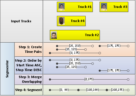
In the second scenario the segmenting logic is more complex. The segmenter first examines the start and stop times associated with all of the overlapping tracks produced by the previous detection action in the pipeline and proceeds to merge those intervals and segment the result. The goal is to generate a minimum number of segments that don't include unnecessary frames (frames that don't belong to any tracks). For example:

"TARGET_SEGMENT_LENGTH" Property
This property indicates the preferred number of frames which will be provided to the detection component. For example, a value of "100" indicates that the input video should be split into 100-frame segments. Note that the properties "MIN_SEGMENT_LENGTH" and "MIN_GAP_BETWEEN_SEGMENTS" may ultimately cause segments to vary from the preferred segment size.
"MIN_SEGMENT_LENGTH" Property
If a segment length is less than this value, the segment will be merged into the segment that precedes it. If no segment precedes it, the short segment will stand on its own. Short segments are not discarded.
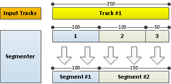
Example 1: Adjacent Segment Present

- In this example, a preprocessor has completed and produced a single track.
- The next detection action specifies the following parameters:
- "TARGET_SEGMENT_LENGTH" = 100
- "MIN_SEGMENT_LENGTH" = 75
- Three segments are initially produced from the input track with lengths corresponding to 100 frames, 100 frames, and 50 frames.
- Since segment 3 is not at least the minimum specified segment length, it is merged with segment 2.
- Ultimately, two segments are produced.
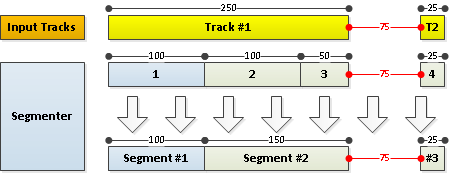
Example 2: No Adjacent Segment

- In this example, a preprocessor has completed and produced two non-overlapping tracks.
- The next detection action specifies the following parameters:
- "TARGET_SEGMENT_LENGTH" = 100
- "MIN_SEGMENT_LENGTH" = 75
- "MIN_GAP_BETWEEN_SEGMENTS" = 50
- The segmenter begins by merging any segments which are less than "MIN_GAP_BETWEEN_SEGMENTS" apart. There are none.
- The segmenter then splits the existing segments using the "MIN_SEGMENT_LENGTH" and "TARGET_SEGMENT_LENGTH" values.
- The segmenter iterates through each segment produced. If the segment satisfies the minimum length constraint, it moves to the next segment.
- When it reaches the third segment and finds the length of 50 frames is not at least the minimum length, it merges that segment with the previous adjacent segment.
- When it reaches the final segment and finds that the length of 25 frames is not at least the minimum length, it creates a short segment since there is no adjacent preceding segment to merge it with.
- Ultimately, three segments are produced.
"MIN_GAP_BETWEEN_SEGMENTS" Property
This property is important to pipelines which contain preprocessors or filters and controls the minimum gap which must appear between consecutive segments. The purpose of this property is to prevent scenarios where a preprocessor or filter produces a large number of short segments separated by only a few frames. By merging the segments together prior to performing further segmentation, the number of work units produced by the segmenting plan can be reduced, thereby reducing pipeline execution time.
Consider the following diagram, which further illustrates the purpose of this property:

- The user submits a video to a pipeline containing a motion preprocessor followed by another extractor (e.g., face).
- The video is initially split into segments using the properties provided by the motion preprocessor. Specifically, the preprocessor action specifies the following parameters and four segments are produced:
- "TARGET_SEGMENT_LENGTH" = "250"
- "MIN_SEGMENT_LENGTH" = "150"
- "MERGE_TRACKS" = "true"
- The segments are submitted to the motion preprocessor, and five distinct and non-overlapping tracks are returned based on the frames of the segments in which motion is detected.
- Because the "MERGE_TRACKS" property is set to "true", tracks are merged across segment boundaries if applicable. This rule is applied to each pair of tracks that are only one frame apart (adjacent). Consequently, only three tracks are ultimately derived from the video. (The number of tracks is reduced from five to three between the "Preprocessor" and "Track Merger" phases of the diagram.) When two tracks are merged, the confidence value will be set to the maximum confidence value of the two tracks and their track properties will be merged. If the two tracks both have a track property with the same name but different values, the values will be concatenated with a semicolon as the separator.
- The non-overlapping tracks are then used to form the video segments for the next detection action. This action specifies the following parameters:
- "TARGET_SEGMENT_LENGTH" = "75"
- "MIN_SEGMENT_LENGTH" = "26"
- "MIN_GAP_BETWEEN_SEGMENTS" = "100"
- The segmenting logic merges tracks which are less than "MIN_GAP_BETWEEN_SEGMENTS" frames apart into one long segment. Once all tracks have been merged, each track is segmented with respect to the provided "TARGET_SEGMENT_LENGTH" and "MIN_SEGMENT_LENGTH" properties. Ultimately, ten segments are produced. (Track #1 and Track #2 in the "Track Merger" phase of the diagram are combined, which is why Segment #3 in the "Segmenter" phase of the diagram includes the 25 frames that span the gap between those two tracks.)